Fanuc System Variables
Fanuc system variables (the #-numbers) are how a custom macro reads and writes the control’s internal state — tool offsets, work offsets, live axis positions, probe results, modal codes, timers, and alarms. A part program treats them like any other variable: read one into a general-purpose variable, do arithmetic, and (where the variable is writable) assign a new value back. This is the mechanism behind every probing routine, tool-breakage check, and adaptive macro on a Fanuc control.
How the Numbering Is Organized
The number itself tells you what family a variable belongs to. Once you know the map, an unfamiliar #-number stops being a lookup exercise:
| Range | Family |
|---|---|
#1–#33 | Local variables & macro call arguments |
#100–#999 | Common (general-purpose) variables |
#2001–#2800, #10001–#13999 | Tool offsets |
#3000–#3902 | Alarms, timers, control switches, counters |
#4001–#4130 | Modal information (active G-codes and addresses) |
#5001–#5108 | Positions (previous block, machine, work, skip, deviation) |
#5201–#5328, #7001–#7948 | Work offsets (external, G54–G59, G54.1 P1–P48) |
Complete Reference
The R/W column is the part most tables leave out — it tells you whether a macro can assign to the variable (R/W or W) or only read it (R). Writing to a read-only variable raises an alarm.
| Variable | Usage | R/W |
|---|---|---|
| Macro Arguments & General Purpose | ||
#0 | Null (vacant) variable — always empty; assignment is not allowed | R |
#1–#33 | Local variables / macro call arguments — a fresh level per macro call (unpassed arguments are null; the caller’s values are restored at M99; initialized to null at power-off) | R/W |
#100–#199 | Common variables, cleared at power-off. Probing software (e.g. Renishaw Inspection Plus) reserves part of this range for measurement outputs when installed | R/W |
#500–#999 | Common variables, retained through power-off. Probe calibration data conventionally lives at the bottom of this range when probing is installed | R/W |
| Tool Offsets — 5-digit numbers (offsets 1–999, every memory type) | ||
#10001–#10999 | Length wear, H-code (base + offset number). On memory type A this is the single combined offset value; on type B, wear (B makes no H/D distinction) | R/W |
#11001–#11999 | Length geometry, H-code (base + offset number); on memory type B, geometry | R/W |
#12001–#12999 | Radius wear, D-code (memory type C only) | R/W |
#13001–#13999 | Radius geometry, D-code (memory type C only) | R/W |
| Tool Offsets — legacy #2xxx aliases (first 200 offsets only) | ||
#2001–#2200 | Alias of #10001+ — memory type A: the offset value; type B/C: length (H) wear by default | R/W |
#2201–#2400 | Alias of #11001+ — length (H) geometry by default | R/W |
#2401–#2600, #2601–#2800 | Radius (D) geometry / wear aliases — exist only in FS15-style numbering (bit 3 V15 of parameter 6000 = 1, plus bit 5 D15 of parameter 6004 on 30i); by default D offsets have no #2xxx alias | R/W |
| System & Control | ||
#3000 | Programmable alarm: #3000 = 1 (MESSAGE) stops the program and displays the message | W |
#3001 | Millisecond timer (counts while power is on; presettable) | R/W |
#3002 | Hour timer (counts while the cycle-start lamp is on) | R/W |
#3003 | Suppress single block / M-function wait (bit-coded) | R/W |
#3004 | Disable feed hold / feedrate override / exact stop (bit-coded, cleared on reset) | R/W |
#3006 | Programmable stop with message: #3006 = 1 (MESSAGE) | W |
#3007 | Mirror-image status per axis (bit-coded) | R |
#3011 | Current date, YYYYMMDD | R |
#3012 | Current time, HHMMSS | R |
#3901 | Machined parts count | R/W |
#3902 | Required parts count | R/W |
| Modal Information (state of the last buffered block) | ||
#4001 | G-code group 01, motion: 0=G00, 1=G01, 2=G02, 3=G03 | R |
#4002 | G-code group 02, plane: 17=G17, 18=G18, 19=G19 | R |
#4003 | G-code group 03: 90=G90 absolute, 91=G91 incremental | R |
#4005 | G-code group 05, feed mode: 94=G94, 95=G95 | R |
#4006 | G-code group 06, units: 20=G20 inch, 21=G21 metric | R |
#4007 | G-code group 07, cutter comp: 40=G40, 41=G41, 42=G42 | R |
#4008 | G-code group 08, length comp: 43=G43, 44=G44, 49=G49 | R |
#4010 | G-code group 10, canned-cycle return: 98=G98, 99=G99 | R |
#4014 | G-code group 14, work coordinate system: 54=G54 … 59=G59 | R |
#4001–#4030 | All other modal G-code groups follow the same pattern (group NN → #40NN); groups run to 22 on 16i/18i and 0i, to 30 on 30i | R |
#4102 | Modal B code | R |
#4107 | Modal D code (active radius offset number) | R |
#4109 | Modal F code (active feedrate) | R |
#4111 | Modal H code (active length offset number) | R |
#4113 | Modal M code | R |
#4114 | Current sequence (N) number | R |
#4115 | Current program (O) number | R |
#4119 | Modal S code (active spindle speed) | R |
#4120 | Modal T code (active tool number) | R |
#4130 | Modal P code (active G54.1 additional WCS number) | R |
| Position Data (axis order X, Y, Z, 4th… within each block) | ||
#5001–#5008 | Previous block end position (programmed endpoint, work coordinates) | R |
#5021–#5028 | Present position, machine coordinates (read with axes stopped) | R |
#5041–#5048 | Present position, work coordinates (read with axes stopped) | R |
#5061–#5068 | Skip position — where the probe tripped during G31, in work coordinates (if the skip input never trips, these hold the block’s programmed end point) | R |
#5081–#5088 | Tool length compensation currently applied | R |
#5101–#5108 | Servo position deviation (following error) | R |
| Work Offsets | ||
#5201–#5208 | External work offset (EXT / common shift applied to every coordinate system) | R/W |
#5221–#5228 | G54 work offsets (X, Y, Z, 4th…) | R/W |
#5241–#5248 | G55 work offsets | R/W |
#5261–#5268 | G56 work offsets | R/W |
#5281–#5288 | G57 work offsets | R/W |
#5301–#5308 | G58 work offsets | R/W |
#5321–#5328 | G59 work offsets | R/W |
| Additional Work Offsets | ||
#7001–#7008 | G54.1 P1 additional work offsets | R/W |
#7021–#7028 | G54.1 P2 additional work offsets (each P adds 20 to the base) | R/W |
#7941–#7948 | G54.1 P48 additional work offsets | R/W |
Generation Notes
The table above uses the classic 8-axis numbering of the 16i/18i era, which most shop-floor references assume. Where the manuals genuinely differ by control family:
| Topic | 0i-B | 16i/18i-B | 30i/31i/32i |
|---|---|---|---|
| Common variables | #100–#199, #500–#999 standard | #100–#149, #500–#531 base; #150–#199 / #532–#999 optional | 100-variable (#100–#149, #500–#549) or 600-variable (#100–#199, #500–#999) option; B Plus adds a retained #98000–#98499 tier |
| Axes per position / offset block | 4 (#5001–#5004 … G54.1 P48 = #7941–#7944) | 8 (#5001–#5008, work offsets #5201–#5328) | 20 (#5001–#5020; skip = #5061–#5080; G54 = #5221–#5240), plus a #100001+ range for up to 50 axes |
| Modal groups | #4001–#4022 | #4001–#4030, plus #4201–#4330 (block executing right now) and #4401–#4530 (block interrupted by an interrupt-type macro) | |
| G54.1 sets | P1–P48 at #7001+; P1–P300 at #14001+ with the 300-set option | Same numbering; #4330 additionally reports the P number of the executing block | |
#3000 alarm | n = 0–200, message ≤ 26 characters, displays as 3000+n | n = 0–4095 when bit 1 (MCA) of parameter 6008 is set (displays as MCnnnn); message up to 60 characters on B Plus | |
| Value range / precision | ±1047, roughly 8 significant digits | IEEE double precision (≈ ±10308) unless bit 0 (F16) of parameter 6008 selects the legacy format | |
One 16i/0i-era wrinkle: #5201–#5328 (and the even older per-axis aliases #2500–#2806) require the workpiece-coordinate-system option on those controls. The #2500-block work-offset aliases were dropped from the 30i numbering — don’t confuse them with the #2001-block tool offsets.
Read-Only vs Read/Write at a Glance
The rule of thumb: variables that report machine state (positions, modal codes, clock, mirror status) are read-only; variables that hold setup data (offsets, common variables, counters, timers) are writable. Getting this wrong is the classic source of “why won’t it write?” confusion — e.g. #5041 (where the axis is) cannot be assigned, but #5221 (where G54 points) can.
| Read-only (report state) | Read/write (you can assign to them) |
|---|---|
Positions #5001–#5108 (previous-block end, machine, work, skip, tool comp, servo deviation) | Common variables #100–#199, #500–#999 |
Modal codes #4001–#4130 (active G/M/T/S/F/H/D and program state) | Tool offsets #2001–#2800, #10001–#13999 |
Clock #3011/#3012, mirror status #3007, null #0 | Work offsets #5201–#5328, additional #7001–#7948 |
Timers #3001/#3002, part counts #3901/#3902, alarm/stop #3000/#3006 (write-only) |
Named System Variables (30i / 0i-F / Plus)
On the 30i family, every system variable in the tables above also has a name. The format is [#_NAME] for scalars and [#_NAME[i]] for indexed families — the whole reference, # included, sits inside square brackets. A name begins with an underscore followed by up to seven uppercase letters, numerics, or underscores, and the subscript can be any expression, with a non-integer result rounded off ([#_ABSIO[1.4999999]] reads #5001; [#_ABSIO[1.5]] reads #5002). Names have been there since the first 30i (Model A), and they beat raw numbers on two counts: they read like what they are, and they survive numbering changes — [#_WZG54[3]] is G54’s third axis whether the control maps it at #5223 or at #100353 in the 50-axis range, and the tool-offset names follow the wear/geometry meaning even when the V15 parameter bit swaps which #2xxx range holds which. The control also polices them: a misspelled or unregistered name raises alarm PS1098 (“NO VARIABLE NAME”), and an invalid subscript raises PS1099.
The curated table below covers the names a mill macro actually reaches for; the full list in the B-64724EN manual runs to well over a hundred.
| Name | Number equivalent | Index | R/W | Meaning |
|---|---|---|---|---|
| Work Offsets (index n = axis number, 1–20 / 1–50) | ||||
#_WZCMN[n] | #5201–#5220; #100301–#100350 | n = axis | R/W | External workpiece origin offset (applied to all coordinate systems) |
#_WZG54[n] | #5221–#5240; #100351–#100400 | n = axis | R/W | G54 workpiece origin offset |
#_WZG55[n] | #5241–#5260; #100401–#100450 | n = axis | R/W | G55 workpiece origin offset |
#_WZG56[n] | #5261–#5280; #100451–#100500 | n = axis | R/W | G56 workpiece origin offset |
#_WZG57[n] | #5281–#5300; #100501–#100550 | n = axis | R/W | G57 workpiece origin offset |
#_WZG58[n] | #5301–#5320; #100551–#100600 | n = axis | R/W | G58 workpiece origin offset |
#_WZG59[n] | #5321–#5340; #100601–#100650 | n = axis | R/W | G59 workpiece origin offset |
#_WZP1[n]…#_WZP48[n] (to #_WZP300 with the 300-set option) | #7001–#7960 (20 per set); #14001–#20000 (P1–P300); #101001–#116000 (50-axis) | n = axis; the G54.1 P number is encoded in the name | R/W | G54.1 Pk additional workpiece origin offset — [#_WZP17[3]] is G54.1 P17, 3rd axis |
| Tool Offsets (index n = compensation number, 1–200 / 1–999) — ranges shown for V15 = 0; V15 = 1 swaps the wear/geometry numbers, the names always follow the meaning | ||||
#_OFSHW[n] | #2001–#2200, #10001–#10999 | n = offset number | R/W | H-code length wear (memory C) |
#_OFSHG[n] | #2201–#2400, #11001–#11999 | n = offset number | R/W | H-code length geometry (memory C) |
#_OFSDW[n] | #12001–#12999 | n = offset number | R/W | D-code radius wear (memory C) |
#_OFSDG[n] | #13001–#13999 | n = offset number | R/W | D-code radius geometry (memory C) |
#_OFS[n] | #2001–#2200; #10001–#10999 | n = offset number | R/W | The single combined offset value (memory A) |
#_OFSW[n] | #2001–#2200, #10001–#10999 | n = offset number | R/W | Offset wear (memory B) |
#_OFSG[n] | #2201–#2400, #11001–#11999 | n = offset number | R/W | Offset geometry (memory B) |
| Positions (index n = axis number, 1–20 / 1–50) | ||||
#_ABSIO[n] | #5001–#5020; #100001–#100050 | n = axis | R | End point position of the previous block (work coordinates) |
#_ABSMT[n] | #5021–#5040; #100051–#100100 | n = axis | R | Current position (machine coordinates) |
#_ABSOT[n] | #5041–#5060; #100101–#100150 | n = axis | R | Current position (work coordinates) |
#_ABSKP[n] | #5061–#5080; #100151–#100200 | n = axis | R | Skip position — where G31 tripped (work coordinates) |
| Interface Signals (index is 0-origin, unlike everything above) | ||||
#_UI[n] | #1000–#1031; #1036–#1067 | n = bit, 0-origin (n = 0–31 → UI000–UI031; n = 32–63 → UI400–UI431) | R | Interface input signal, one bit |
#_UO[n] | #1100–#1131; #1136–#1167 | n = bit, 0-origin | R/W | Interface output signal, one bit |
#_UIL[n] | #1032–#1035; #1068–#1071 | n = 32-bit word, 0-origin (0 = UI000–UI031, 1 = UI100–UI131, …) | R | Interface input signals, 32 points at a time |
#_UOL[n] | #1132–#1135; #1168–#1171 | n = 32-bit word, 0-origin | R/W | Interface output signals, 32 points at a time |
| Clock & Date | ||||
#_CLOCK1 | #3001 | — | R/W | Clock 1 (milliseconds) |
#_CLOCK2 | #3002 | — | R/W | Clock 2 (hours) |
#_DATE | #3011 | — | R | Year/Month/Date |
#_TIME | #3012 | — | R | Hour/Minute/Second |
| Alarm & Message | ||||
#_ALM | #3000 | — | W | Macro alarm |
#_MSGSTP | #3006 | — | W | Stop with a message |
| System Constants | ||||
#_EMPTY | #0, #3100 | — | R | Null (the vacant value) |
#_PI | #3101 | — | R | Circular constant π = 3.14159265358979323846 |
#_E | #3102 | — | R | Base of natural logarithm e = 2.71828182845904523536 |
| Execution Control — per-bit names (no numeric per-bit equivalent exists) | ||||
#_M_SBK / #_M_FIN | bits 0 / 1 of #3003 | — | R/W | Enable/disable suppression of single block stop / waiting for the auxiliary function completion signal |
#_M_FHD / #_M_OV / #_M_EST | bits 0 / 1 / 2 of #3004 | — | R/W | Enable/disable feed hold / feedrate override / exact stop check |
| Modal Information | ||||
#_BUFG[n] | #4001–#4030 | n = G-code group number | R | Modal G code of the last buffered block |
#_ACTG[n] | #4201–#4230 | n = G-code group number | R | Modal G code of the block currently being executed |
#_BUFF / #_BUFS / #_BUFT / #_BUFM | #4109 / #4119 / #4120 / #4113 | — | R | Modal F / S / T / M of the last buffered block; the #_ACT… forms (#4309 / #4319 / #4320 / #4313) report the executing block |
Side by side, the number form and the name form of the same reads and the same probe write (this is the “touch off and set zero” pattern worked in full in the next section — Z is axis 3, so [#_WZG54[3]] is #5223 and [#_ABSKP[3]] is #5063):
(READ G54 Z - NUMBER FORM, THEN NAMED FORM)
#101 = #5223
#101 = [#_WZG54[3]]                          (INDEX 3 = Z, THE 3RD AXIS)

(PROBE TOUCH-OFF WRITE, NAMED FORM)
G90 G31 Z-25. F50.                           (FEED DOWN UNTIL THE PROBE TRIPS)
[#_WZG54[3]] = [#_WZG54[3]] + [#_ABSKP[3]]   (SHIFT G54 Z BY THE SKIP Z)
G00 Z25.                                     (RETRACT)
Because the subscript takes any expression, the indirect-addressing tricks later in this article carry straight over — [#_ABSKP[#500*2]] is legal. The lathe-side names (#_OFSXW, #_OFSZG, #_WKSFTX and kin) are mapped in the Fanuc Turning System Variables article.
Reading & Writing System Variables in a Macro
Read the current work coordinate and motion mode, then decode them:
#100 = #4001   (active motion mode: 0=G00, 1=G01, 2=G02, 3=G03)
#101 = #4014   (active work coordinate: 54-59)
#102 = #5041   (current X in the work coordinate system)
#103 = #5021   (current X in machine coordinates)
Probe a surface and write the result to a work offset. This is the core “touch off and set zero” pattern: feed down with G31 until the probe trips, then shift the G54 Z offset (#5223) so the touched face becomes Z0 in that work coordinate system. (#5061–#5068 hold the skip position in work coordinates; the axis order is X, Y, Z…, so Z is #5063.)
(TOUCH TOP OF PART, SET IT AS G54 Z0)
G90 G31 Z-25. F50.        (feed down until the probe trips)
#5223 = #5223 + #5063     (shift G54 Z so the touched face = Z0)
G00 Z25.                  (retract)
Measure a tool on a tool setter and write its length offset. The same skip mechanism, but the write target is a tool geometry offset, addressed indirectly so one macro serves every tool. #500 holds the calibrated trigger height of the setter (a retained common variable, set once during calibration):
(MEASURE TOOL LENGTH ON A TOOL SETTER)
#1 = 5                      (tool / H number being measured)
G91 G31 Z-400. F200.        (first touch, fast)
G01 Z2.                     (back off)
G31 Z-4. F30.               (second touch, slow, for repeatability)
#[11000 + #1] = #5063 - #500  (geometry offset = skip Z minus setter height)
G91 G28 Z0.                 (home Z)
Indirect addressing also works on the read side — here, checking the geometry length offset for whatever H-code is currently active:
#104 = #[11000 + #4111]   (geometry length offset for the active H number)
IF [#104 GT 6.0] GOTO 10  (branch if the tool is unexpectedly long)
Gotchas Worth Knowing
- Look-ahead buffering. The control reads blocks ahead of the one executing. A macro block that reads position or modal state can be evaluated before the preceding motion finishes — and a block already in the buffer keeps the old value of a work offset you just wrote. Where the read/write must be synchronized with motion, force the buffer to drain first (a
G04dwell or a G53 positioning block are the common idioms). - Read positions with the axes stopped. The manuals mark
#5021–#5028and#5041–#5048as “read operation during movement: disabled” — because of the buffering (pre-read) function, a value read mid-move is not guaranteed to be the expected one. The exception is the skip block:#5061–#5068are latched at the instant theG31input trips, which is exactly why probing macros read those instead of#5041. - Tool offset numbering depends on the memory type — and one parameter bit. The five-digit
#10001+blocks are the safe choice: they exist on every memory type and cover offsets 1–999. The four-digit#2001+numbers are aliases for the first 200 offsets only, and what they mean shifts with memory type (on type A,#2001is the whole offset; on B/C it is the wear register by default). On top of that, bit 3 (V15) of parameter 6000 swaps the wear/geometry assignment across the whole map to match FS15 conventions — and some builders ship it set. Write a known value from MDI and read it back before trusting hard-coded numbers. - The null variable
#0is not zero. An unset (vacant) variable equals#0, andIF [#7 EQ #0](is it vacant?) behaves differently fromIF [#7 EQ 0](is it zero?). A vacant variable used in arithmetic is treated as 0, which silently masks a missing macro argument — test against#0when an argument is optional. #3000stops the program;#3006pauses it. Use#3000 = n (TEXT)for a hard fault (operator must reset) and#3006 = 1 (TEXT)for a planned operator interaction (cycle start continues).
▶ Try these in the Macro Playground — pick the Fanuc control, type a macro, set the system-variable inputs (like #5063), and watch the values update live as it runs.
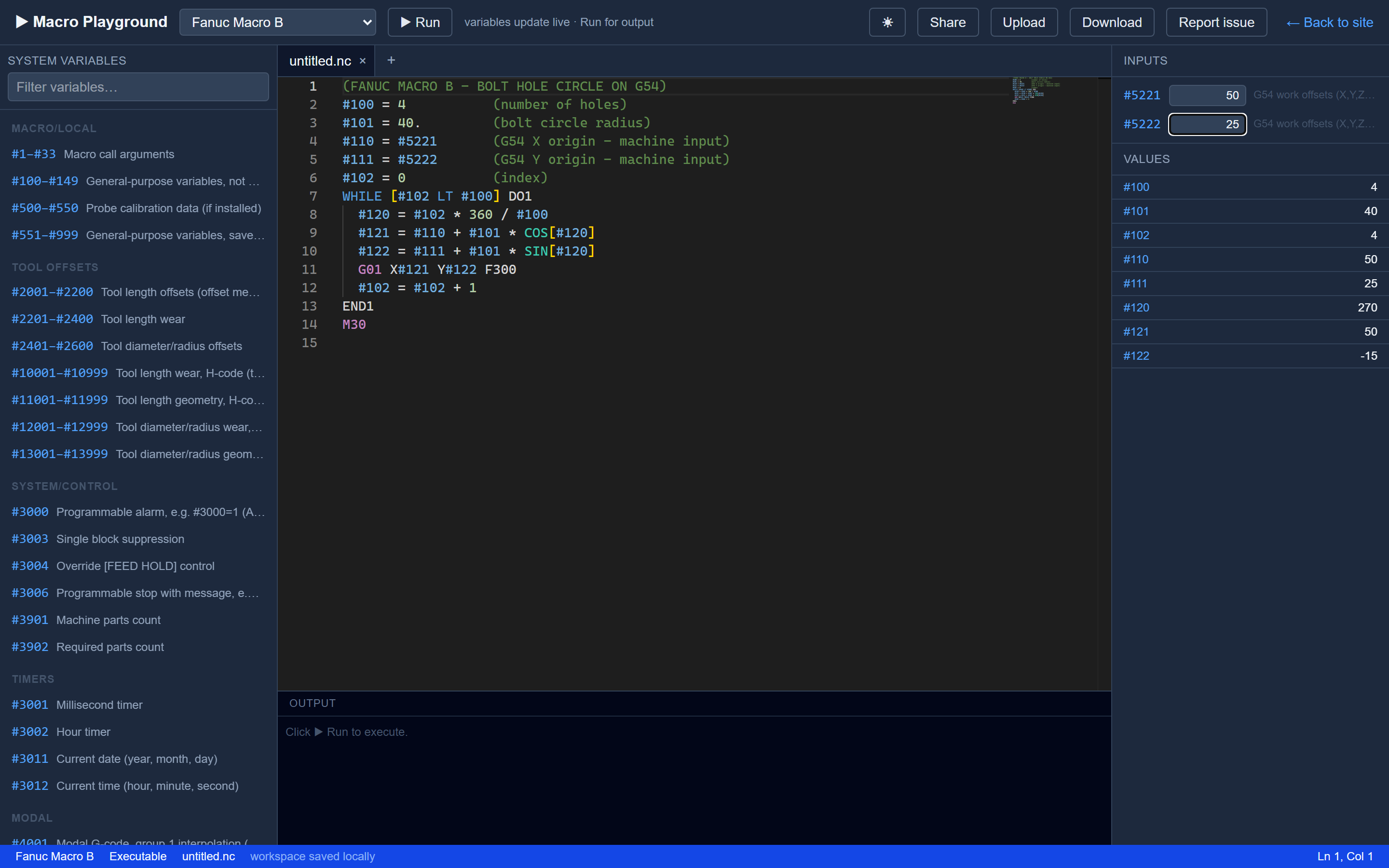
The playground’s variable sidebar is built from this reference — read-but-never-written variables (like the #5221 G54 origin here) automatically become machine inputs you can set.
See also: Reading & Writing System Variables for the same probe-to-offset chain on every control, Modal & Position Data for the #4001/#5001 families in depth, Tool Offset Variables for offset-memory details, and Custom G/M Cycles for packaging these reads and writes into a reusable cycle.
References
- FANUC, Series 30i/31i/32i-MODEL B Plus Operator’s Manual (Common to Lathe System / Machining Center System), B-64724EN/01, Ch. 16 “Custom Macro”.
- FANUC, Series 30i/31i/32i-MODEL A User’s Manual (Common to Lathe System / Machining Center System), B-63944EN/03, Ch. 16 “Custom Macro”.
- FANUC, Series 16i/18i/160i/180i-MODEL B Operator’s Manual (Machining Center), B-63534EN/02, Ch. 15 “Custom Macro”.
- FANUC, Series 0i-MODEL B Operator’s Manual (Machining Center), B-63844EN/02, Ch. 15 “Custom Macro”.
- Peter Smid, Fanuc CNC Custom Macros, Industrial Press, 2004.
Have a question or want to contribute?
Contact us with corrections, additions, or topics you'd like covered.
Get in Touch